 SETI League Technical Manual -- Antennas
Copyright © 1997 by Dr. H. Paul Shuch, N6TX
Executive Director, The SETI League, Inc.
PO Box 555, Little Ferry NJ 07643
email n6tx @ setileague.org
The non-profit, membership-supported SETI League, Inc. is an international alliance of radio hams and amateur radio astronomers, seeking to privatize a scientific Search for Extra-Terrestrial Intelligence once conducted by NASA. [1] Its Project Argus sky survey went on the air on 21 April 1996, initially with five participating stations in North America and Europe. [2] One year later, the search phase boasted 28 participating stations on five continents, with many other stations under construction in 30 different countries.
The antenna used in our first Project Argus stations suffered from low illumination efficiency and relatively high noise temperature, due primarily to the simple cylindrical waveguide feedhorn employed. The addition of a single choke ring around an existing feedhorn can improve overall system performance by more than 1 dB. Figure 1 shows the author with the prototype of a new SETI feedhorn, which has been duplicated by several of our members, and is also commercially available.
|
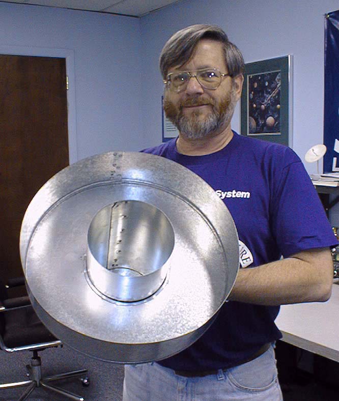 SETI League photo |
| Dimension | cm | inches |
| Inside Diameter of Waveguide | 15.6 | 6.14 |
| Total waveguide length | 27.8 | 10.94 |
| Inside Diameter of Choke Ring | 36.0 | 14.17 |
| Depth of Choke Ring | 10.6 | 4.17 |
| Length of Coax Probe | 4.6 | 1.81 |
| Placement of Coax Probe | 8.8 | 3.46 |
The final dimension above is measured with respect to the shorted end of the waveguide. See Figure 2 for details of the quarter-wavelength monopole probe.
To download a Microsoft Excel ® spreadsheet for computing dimensions for feedhorns as a function of frequency and selected waveguide diameter, click here.
|
SETI League drawing |
Feedhorn dimensions are typically selected to illuminate the surface of a dish as fully and uniformly as possible, to achieve the highest possible antenna gain. Industry practice is to utilize a 10 dB edge illumination taper. That is, with respect to the center of the dish, signals reaching the feed from the very edge of the dish are 10 dB lower in amplitude. With simple cylindrical waveguide feedhorns, the result is typically a 55% efficient antenna system. For most communications applications, where range and margin are a function of recovered signal strength, this is indeed an appropriate design technique.
SETI, on the other hand, is a unique application in that the strength of the anticipated receive signal is entirely unknown. Our range and sensitivity are largely noise- limited. That is, in order to maximize our sensitivity, we need to reduce antenna noise temperature to the absolute minimum. This can be accomplished by deliberately under-illuminating the dish. Let's calculate an example based upon a 5 meter parabolic reflector operating at the 1420 MHz Hydrogen line. If we use a 15 dB illumination taper, the antenna gain goes down almost one dB (from +34.8 to +34.0 dBi), as efficiency drops to say 45%. But for a SETI system with a low noise front end, reducing antenna gain and efficiency actually improves sensitivity. Here's how:
Let's imagine our receiver uses a GaAs PHEMT front end, running at 50 K receive noise temperature. With a dish designed for optimum gain, the antenna noise temperature, dominated by Earth-seeing sidelobes, is about 50 K. The overall system noise temperature is thus 100 K, and sensitivity (given 10 Hz bin width and 10 second integration) is on the order of 1.3 E-22 W/m^2. Now under-illuminate for 10 K of antenna noise. Antenna gain decreases 0.8 dB as discussed above, but overall noise temperature reduces to 60 K, a 2.2 dB decrease in noise. System sensitivity is now 9.4 E-23 W/m^2, a net system improvement of 1.4 dB!
Is the cited sensitivity adequate to the task of meaningful SETI? In 1977, NASA SP-419, The Search for Extraterrestrial Intelligence articulated this goal on page 21: "Existing antennas could be used to search ... the entire microwave window to as low as ~10 E-23 W/m^2 in a few years of observing time." By increasing to 120 seconds the integration time constant of the system just described, overall sensitivity improves to on the order of 2.7 E-23 W/m^2. Thus, two decades later, amateur SETI is just now closing in on NASA's sensitivity goal for SETI sky surveys.
The chief determinant of illumination taper for scalar-ring feedhorns is the placement of the choke ring along the waveguide feedhorn. The choke ring must be designed so as to slide back and forth on the waveguide horn, in order to optimize the illumination pattern of the feed for noise vs. gain, as well as the particular focal length to diameter ratio (F/D) of the dish being used. Here are the critical dimensions for the distance between the front of the horn and the back of the choke ring. They are shown in Table 2 for dishes of various F/D ratios, for both lowest antenna noise temperature (the preferred condition for SETI) and greatest antenna gain (which you would choose for a transmit antenna). All dimensions are in cm (inches).
| F/D = | 0.50 | 0.45 | 0.40 | 0.35 | 0.30 | 0.25 |
| LoNoise | 8.52 (3.35) | 9.08 (3.57) | 10.6 (4.17) | 11.36 (4.47) | 12.4 (4.88) | 12.8 (5.04) |
| HiGain | 10.08 (3.97) | 10.6 (4.17) | 11.6 (4.57) | 12.4 (4.88) | 13.2 (5.20) | n/a |
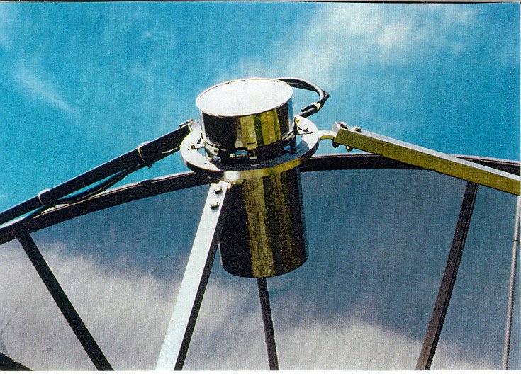
Figure 3 shows how shows how Project Argus pioneer Magin Casanitjana, EA3UM added a choke ring to his antenna feeds. It also illustrates how dual feedhorns can be accommodated by mounting one horn slightly offset from the focal point of the dish. This approach skews the antenna pattern slightly, but the result is easily measured by peaking the antenna on sun noise, and compensating aiming accordingly. Such a dual feedhorn design is a viable alternative for those members wishing to use a single dish simultaneously for satellite TV reception and SETI.
An alternative method of mounting a feedhorn to a dish is seen in Figure 4.
|
EA3UM photo |
|
 WA7CRE photo |
a = (d * f) / D - (d * D) / (16 * f)Note that a, d, D, and f are all measured in the same units.where:
a = distance the focus should be inside the feedhorn
D = diameter of the dish
d = diameter of the feedhorn (not of choke ring)
f = focal length of dish.
Since the feedhorn just described was scaled from an EME design, we now return to the moonbounce application, and challenge a basic principle of antenna design: that of reciprocity. It's widely held that an antenna will function equally well in receive and transmit modes. This is because, to a first order approximation, antennas are impedance matching transformers, matching the characteristic impedance of a feedline (typically 50 ohms) to that of free space (120 pi, or about 377 ohms). We depend upon the principle of reciprocity when we measure the gain of transmit antennas on the antenna range, by receiving a test signal through them.
To be sure, passive impedance matching networks are bi-directional, and the primary function of antennas is to match impedances. But the secondary function of any but an omnidirectional antenna is to direct energy, and the directivity needs of transmit and receive systems may well differ. Such is certainly the case in EME communications.
Consider that when transmitting toward the Moon (or anywhere else), our primary objective is to maximize effective isotropic radiated power (EIRP) in a desired direction. If using a parabolic reflector for transmit, we would then choose to illuminate the reflector for maximum power gain. The optimum illumination taper should tend to minimize sidelobes (on the principle that sidelobe power is wasted power), but the optimum feed illumination for forward gain is not necessarily that which minimizes sidelobes.
In receive mode, we have shown system sensitivity to be a function of both antenna gain and noise temperature. Our calculations indicate that optimum performance can result if we sacrifice some gain for a reduction in sidelobes. Again, the optimum feed illumination for sidelobe reduction is not necessarily that which maximizes forward gain.
It then appears that for EME, the optimum choke ring placement, as seen in Table 2, varies between transmit and receive use. SETI League president Richard Factor, WA2IKL, has suggested an unconventional approach to feedhorn design for EME use. He proposes a design wherein the choke ring be mounted to the cylindrical feedhorn on a track, allowing the choke to be readily slid fore and aft during use. The assembly would then be motorized, with mechanical stops, such that the choke ring is positioned toward the back of the horn (that is, in highest gain position) during transmit cycles, and forward (to the low noise position) for receive. The mechanical switching time should not present EME operators with any difficulty, considering that EME echo time is just over two seconds, and that transmit/receive sequences typically range from 30 seconds to 2 minutes, depending on the band used.
At present, I have not physically implemented Richard's suggestion, but it seems almost trivial to do so. I invite participants at Microwave Update '97 to experiment with this variable feedhorn geometry in their EME stations, and report their results at next year's meeting.
References
[1] Shuch, H. Paul, Searching for life among the stars. QST 79(8): 37-39, August 1995.
[2] Shuch, H. Paul, Project Argus and the challenge of real-time all-sky SETI. Proceedings, 30th Conference of the Central States VHF Society: 62-69, American Radio Relay League, July 1996.
[3] Malowanchuk, Barry, VE4MA 5760 MHz Linear Polarization Feedhorn. Proceedings of Microwave Update '95: 214. October 1995, ARRL.
email the Webmaster | entire website copyright © The SETI League, Inc. this page last updated 4 January 2003 |
Top of Page |