SETI League Technical Manual -- Receivers
The Icom model R-7000, R-7100, R-8500, and PRC-1000 scanning microwave receivers are gaining popularity among SETI League members. Their chief drawback is an Automatic Gain Control (AGC) circuit which cannot be turned off. AGC effectively reduces the sensitivity of your Digital Signal Processing (DSP) program by making weak signals stronger, and strong signals weaker. Several different modification strategies are described here, which will not only disable AGC, but (with the exception of the last one) will most assuredly void any receiver warranty. In addition, the modification will render your signal strength meter ("S-meter") inoperative. SETI League members performing any of these modifications do so at their own risk.
These modification instructions by SETI League member and Project Argus participant Rich Tyndall, NJ1A (email nj1a_at_erols_dot_com) allow you to disable AGC in the Icom R-8500. They involve removing (actually, destroying) one chip capacitor on the receiver's main board
Notice: Read and understand this document before attempting the modification.(FYI: Your warranty maybe adversely effected).
Warning: The main board could be damaged by static electricity. Be sure to wear a ground strap after the top cover is removed.
- Remove any power, audio, RS-232 & etc. cables plugged into the rear panel.
- Remove top cover per steps 1 and 2 on page 37 of manual. (Ten #2 phillips screws). Lift the cover off slowly being careful not to break the speaker cable, Unplug it from main board.
- Remove 13.8 DC Power connector by squeezing the retaining clips on each side of connector while pushing in from the rear. (It may be tight).
- Remove all the #2 phillips screws holding down the main board.
- Remove the two #1 phillips screws holding down the RS-232 connector.
- Remove the steel heat sink clip holding down 13.8 VDC power cable.
Note: In order to lift the main board up to do the mod without removing too many cables, you will need to provide slack in some cables and unplug the ribbon cables.
- Un-bend the metal cable holder clips near the white ribbon cables to provide the necessary slack. (These clips hold small coax etc).
You could use a pen to make a line on the ribbon cables, so you will know how far to push them back in during reassembly.
- Un-plug the (4) white ribbon cables by:
(A) Gently lifting up (2 mm) on the locking tabs on each end of the connectors until they are in the UP position.(B) Grasp the white ribbon cable on both sides and pull it out of the socket.
- Grasp the large metal (filter) clip in the center of the board and lift. (If the board does not move, you missed a screw).
- You must lift the board at an angle and then towards the front panel, so as to allow the long RCA sockets in the rear panel to clear their holes.
- Once the rear of the main board can be lifted and flipped over, you can locate C-114 and perform the mod by cutting the center of C-114 in with small wire cutters. [Caution: Wear safety glasses]. Use a tooth brush to clean the site, then inspect it with a magnifier to ensure the AGC RF path is now open.
Hardware Reassembly:
Reverse the above steps.Reassembly Notes:
Before replacing the main board screws, check around the sides to insure that you don't pinch any cables under the edges. (Watch those cables bundled with the +12VDC cable).
Be sure that the locking tabs on both ends of the ribbon cable sockets are in the UP position before plugging the flat cables back in. As you apply down pressure, you will feel some resistance and then the cable will 'Click in' and bottom out in the socket. Push down on both ends of the locking tabs until they snap into locked position.
Testing Mod:
After reassembly, tune the R-8500 to a strong signal, you should not see any S-meter movement except in the WFM mode.
Random notes:
Don't try to save C-114. If you did want to reverse this mod at some later date, I recommend using a new part. (Not one that may have been damaged by heat).
If you have any questions regarding the hardware disassembly/reassembly, email Rich Tyndall, RTyndall_at_juno_dot_com.
After following Rich's instructions, Chris Dapples, KF7KN (email ccdapple_at_wtp_dot_net) adds:
Following the modification as posted to the SETI League receivers section for the Icom IC-R8500 involves cutting a SFM capacitor (C114) This permentially disconnects the AGC function in AM, SSB and CW modes. However, I have found a way to install a switch to allow AGC disconnect as wanted.Step 1: prepare a small toggle switch with about 12 to 15 inches of mini-coax or twisted pair will work too. I used a Radio Shack micro-mini SPDT toggle switch (RS 275-625). Prepare and tin about 3/8 inch of the wire to connect to the main circuit board of the 8500.
Step 2: Remove the main circuit board as per the already posted instructions. Place the board upside down in front of you with the rear edge (with the RS232 connector) nearest to you. Measure exactly 4 inches from the left card edge and 15/16th of an inch back from the nearest card edge (with RS232 connector). You should find at this point a trace that is an inverted and backwards "L" shape with C114 on the short leg and the double diode (D20) chip on the long leg. Just below the diode chip (nearer you) the trace splits into to two parallel traces and there are two feed-thru hole at the coordinates you measured. Clean the copper of these holes and carefully solder the ends of the mini- coax to these holes.
Step 3: While the main circuit board is out of the receiver case use a reamer or drill (3/16) to enlarge one of the long slots just to the left of the 12VDC connector to receive the switch. Be sure to remove any metal filings that result from the drilling.
Step 4: Replace the main circuit board to the receiver case routing the wires to the switch to the front side of the board and than back across the top of the board, There are several convenient notches in the circuit board where the ribbon cables connect where the wires can come from underneath with out binding. Replace the ribbon cables, but before fastening down the screws power up the receiver and tune a strong signal. The switch should toggle the AGC on and off as indicated by the S-meter showing a strong signal when the AGC is active and showing nothing when the AGC is deactivated. If everything is working and there are no shorts of your switch wires to the case under the circuit board screw everything down and replace the cover.
Step 5: Pat yourself on the back for completing a good job!
Randy Stegemeyer (email hamradio_at_oz_dot_net) is using the older Icom R-7000 receiver. He writes:
I disabled the AGC on my R-7000 by cutting the top lead of R-115 on the IF board. This resistor is in the base lead to transistor Q18, which is the AGC amplifier. With this resistor opened, no voltage from the AGC rectifier diode D28 can reach Q18 so it never attempts to lower the gain of the receiver. After you take the top cover off, and facing the front of the receiver, R-115 is located about 5 inches from the left side of the receiver, and about 4 inches from the front. Its plainly marked and is standing on end. The lead coming out of the top is easy to clip and easy to solder back if you need to. I never use my R-7000 in AM mode for anything other than radio astronomy so I did not add a switch for turning it on and off, but it would be a simple matter to do so.My modification seems to be working fine for me but I would be interested in hearing from anyone with problems or a better idea.
Norm White (email NOREX_at_mcia_dot_net) has come up with the most elegant AGC mod to date for the Icom R8500 receiver. He writes:
Being somewhat lazy and not wanting to disassemble my new R8500, I have designed a new method to disable the AGC externally. The agc driver Q27 is a weak voltage source of greater than 1K ohm impedance. This voltage source can very easily be overcome by a low power regulator. I have used a Toko TO92 regulator part # TK11625. This +2.5v regulator is available from Digikey for $1.30.Maximum gain in the R8500 is at an AGC voltage of 2.4V. I have built this strong voltage driver in an RCA phono jack. I get the input power from the 13.8v DC connector on the back of the receiver. I can now disable the AGC by just plugging in the driver into the AGC RCA phono jack on the back of the R8500.
A schematic diagram of this modification appears below.
Steve Woodruff, Electronics Technician at Hanover College, sends along this information:
To disable AGC function in WFM mode on the IC-R8500, short between the base of Q6 and ground on the MAIN board.
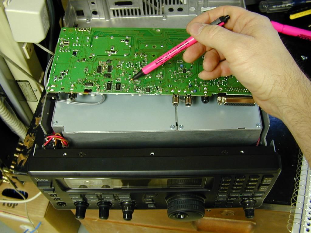
To disable the AGC function in FM, AM, SSB, and CW mode, short circuit between the base of Q27 and the emitter of Q27 on the MAIN board. (Here's a photo showing the location of Q27. Click on the thumbnail to view the full-size image.)
I received this information by calling Icom tech support. The friendly tech faxed me a Schematic and the above instructions. It also included something about not being a factory authorized mod resulting in "not guarantee the specification with this mod."
From Argus station JO89sn in Sweden, Greg writes:
Decided to do something about the AGC in the Icom PCR-1000 unit, the agc is always activated, the only selection is fast or slow agc - no way to disable it. I'm not going to debate the benefits of disabling the agc, that's another story.After some schematic studying and testing I found there are no way to easily disable it, won't work by cutting any tracks or injecting 2.5v as in the R8500 unit. I decided to go for another approach in which I shift the agc op voltage reference, this is done by replacing a resistor in the voltage divider prior to the op, this way the signal is just dc voltage and makes it able to switch using a relay and wires.
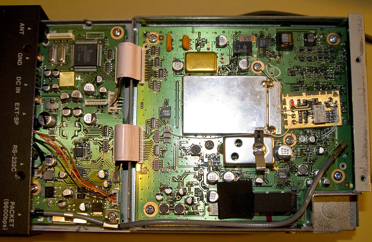
However I didn't want to permanently change the agc as I use the radio for other stuff as well, so I made a little cockroach to make this option avaible by software. This photo shows the mod (now the board is fixed and wires are trimmed). Click on the thumbnail for a high resolution image.
I just activate the AGC button (which normally switch to fast agc) to activate it, so it will work with any standard control software. A schematic can be found in this Portable Document Format file. The led part is optional, was only for testing purposes.
Any questions/ideas can be forwarded to me at greger_at_rfelektronik_dot_se.
I also replaced some capacitors in the voltage regulator circuit, the linear regulators get very very hot, as do the caps next to them, so I changed them before they dry up and also added some extra to reduce ripple created by cheap switching adaptors. You can see the pcb discoloring due to the heat, they really should have heatsinked the regulators.
email the Webmaster | entire website copyright © The SETI League, Inc.; Maintained by Microcomm this page last updated 14 July 2007 |
Top of Page |