 Publications Department
Reviewing the design criteria of the basic Project Argus amateur radio telescope shows that it achieves sensitivity on a par with the very best professional facilities of a quarter century ago. The challenges of SETI verification and global participation are discussed. Several interesting candidate signals are shown (none of which passed our rigorous tests for intelligent extra-terrestrial origin). Extrapolating current Project Argus technology into the next few decades, we begin to contemplate arraying multiple amateur radio telescopes into a coordinated array of planetary proportions.
INTRODUCTION
The SETI League, Inc. launched its Project Argus all-sky survey in April 1996, with the ambitious goal of real-time all-sky coverage. This SETI experiment is unique in that it employs the talents and energies of thousands of dedicated amateur radio astronomers worldwide. In its first four years, Project Argus has grown from five small prototype radio telescopes to one hundred operational stations, with hundreds more under construction. We are still decades away from our projected 5,000 stations able to see in all directions at once. Nevertheless, much has been learned about how to build radio telescopes on the cheap, operate them with the utmost of professionalism, and interpret received data with scientific rigor.
SKY COVERAGE VS. SENSITIVITY
The Project Argus concept is built around the use of discarded home satellite TV dishes of three to five meters in diameter. [1] When properly illuminated for minimum sidelobes at L-band, such antennas exhibit a 3 dB beamwidth on the order of 4 degrees. Thus, each antenna will subtend just over two milli-steradians of sky, and a properly coordinated network of 5000 such instruments is sufficient to cover the entire four pi steradian celestial sphere.
Although larger dishes would afford greater antenna gain, hence improved sensitivity and range, economic tradeoff analysis favors these more modest instruments if our goal is to achieve full sky coverage.
The available receive circuitry, coupled with the specified antennas, yields a threshold sensitivity of 10^23 watts/meter^2 in the 1.3 to 1.7 GHz "water hole" spectral region. This sensitivity is on a par with that of the Ohio State University "Big Ear" radio telescope during its long-running all sky survey. [2] Further, it is on a par with the sensitivity contemplated for a NASA all sky survey effort during its early planning stages. [3]
ARGUS TELESCOPE OVERVIEW
Project Argus is a global endeavor with participants in 59 countries. Because of differences in equipment availability, there is no "standard" Project Argus hardware package, and each participating member employs such equipment as he or she may have access to locally. Nevertheless, system performance criteria have been established, and a target configuration specified, as seen in the diagram on the next page. The following sections discuss briefly the various items shown in the block diagram, Figure 1. For further details, see The SETI League Technical Manual. [4]
PARABOLIC REFLECTOR
As mentioned above, by far the favored antenna for amateur SETI use is the parabolic reflector ("Dish"). The chief advantage of the parabolic reflector is that it operates over an extremely wide range of frequencies. It is limited at the low end by its diameter (which must be a respectable multiple of the longest wavelength being received, to provide reasonable gain), and at the high end by its surface accuracy (which must not deviate from the parabolic shape by more than a small fraction of the shortest wavelength being received, to maintain reasonable efficiency).
Typical satellite TV dishes generally provide reasonable performance over the 1 to 10 GHz portion of the microwave window. For reception in the 1.4 to 1.7 GHz region which is highly favored for much amateur SETI activity, the optimum dish size is on the order of three to five meters in diameter. In countries such as the US and Canada, where C-band satellite television distribution has been widely used for two decades, suitable dishes are abundantly available at low to no cost. In other parts of the world they are harder to come by, and enterprising SETI League members have acquired surplus commercial telecommunications dishes, or even built their own from scratch.
The size of the dish and the operating wavelength together determine antenna gain. As a first order approximation, the voltage gain (as a ratio) is equal to the circumference of the reflector, measured in wavelengths. Consider, for example, a 3 meter dish, which has a circumference of (3 * pi) = about 9.4 meters. At the 21 cm resonant wavelength of neutral hydrogen atoms (corresponding to the popular SETI frequency of 1420 MHz), the voltage gain of this antenna would approach (940/21) ~ 45. Since power ratio equals voltage ratio squared, the power gain of such an antenna would be about 2,000, which equates to +33 dBi of gain. (In fact, since the efficiency of amateur SETI antennas is generally on the order of 50%, the actual gain realized is more like +30 dBi.)
Dish size also determines beamwidth, which dictates the degree of aiming precision required when targeting specific stars. As an approximation, half-power beamwidth in radians equals wavelength divided by antenna diameter. Thus, for our prior example of a 3 meter dish operated at 21 cm, the beamwidth is on the order of (21/300) ~ 0.07 radians, or 70 milli-radians, which is about four degrees.
For those choosing to obtain a surplus antenna, dish condition becomes an important factor. The main consideration here is surface accuracy. In order to perform up to expectations, a dish's surface cannot deviate from the parabolic by more than a tenth of a wavelength. At 1420 MHz, that's about 2 cm of allowable surface error. If the surface of the dish is dimpled, dented, or distorted beyond 2 cm, avoid that dish! We look for something which approximates a smooth parabolic curve. If panels are missing or bent, performance is going to suffer. Next, we consider at the mounting hardware. If it's rusted, you're going to have trouble getting the dish apart, and more trouble reassembling it. Weight is sometimes a consideration, as is wind loading. Where these are concerns, a mesh dish may prove more realistic than a solid one.
Few of the accessories which come along with a satellite TV dish are useful for SETI, and therefore one should not pay extra for them. C-band or Ku-band feedhorns and preamps are only of value if one is going to search in C-band or Ku-band (some of our members do; most prefer to scan the water-hole, in L-band.) TVRO receivers are great sources of microwave components, but unless other civilizations utilize exactly the same TV transmission standards we do, they're not particularly useful as SETI receivers. And a motorized mount which tracks the Clarke (Geosynchronous) orbital belt is of no value for drift-scan, meridian transit mount radio telescopes, except if modified for elevation rotation, as described below.
ANTENNA MOUNT
The beauty of mounting a parabolic antenna for SETI use is that you just can't go wrong. Since we are interested in monitoring the sky for artificial signals from beyond, the antenna merely need be pointed up -- there are stars (with potentially habitable planets) to be found in all directions. So mounting an antenna for SETI use is considerably simpler than, for example, using the same antenna for satellite TV, where it must be precisely aimed at the satellite's location in the sky.
Because there are no wrong directions for SETI, many SETI antennas are simply set on the ground, "bird-bath" style, looking straight up. But a disciplined sky survey, such as The SETI League's Project Argus effort, requires coordinated sky coverage, and that in turn necessitates a limited steering ability for at least some of the antennas in the network.
Where steering of the antennas is desired, we need to consider two degrees of freedom: azimuth (the compass heading to which the antenna points), and elevation (the angle which the antenna's beam makes with respect to the horizon). In terms of celestial coordinates, azimuth of a radio telescope (along with a station's latitude and longitude, and the date and time) determines the Right Ascension (RA) of its target, while elevation (again, along with lat/lon, time and date) determines Declination (Dec).
Since we live on a rotating planet, the Earth herself makes a most cost effective RA rotor, as long as we are willing to be patient and let the proper portion of the sky eventually rotate into view. But since (thankfully!) the Earth doesn't rotate north-to-south, the only way to achieve Dec control is to physically rotate the antenna along a north-south line. This can be accomplished by aligning a satellite TV antenna's position rotor as a vertical (elevation) rotor.
When antenna rotors are desired, the dish positioners commonly used for satellite TV will require some source of power. The operating voltage for these positioners can often be supplied by a surplus C-band satellite TV receiver, which may also have a digital readout of dish position. Alternatively, a separate DC power supply can be used. The required voltage is typically 24 to 36 VDC, and these rotors draw anywhere from one to four amperes. Polarity determines the direction of rotation, so switching should be provided to move the dish both up and down (or alternatively, both right and left).
FEEDHORN
When radio waves strike a dish antenna, the parabolic shape of its reflector directs all the energy to a single point out in front of the dish, called its focus. The purpose of the feedhorn, which is mounted at the focus, facing the reflector, is to scoop up all this energy, and apply it to the LNA and receiver (both discussed below) for processing.
The most common feedhorn for amateur SETI use is a metal pipe, closed off at the end farthest from the dish, forming a shorted cylindrical waveguide. The horn contains a small metallic probe, connected to the center pin of a coaxial connector, to collect the energy and apply it to the input connector of the LNA. The horn is often surrounded by a metal choke ring, used to improve the efficiency of energy collected from the surface of the dish, or to block interference from entering the feed from beyond the periphery of the dish.
The chief drawback of the cylindrical waveguide feedhorn is that its large physical size actually blocks a part of the dish surface from view of its incoming signals, effectively reducing the size (and hence the gain) of the parabolic antenna. This blockage loss is most severe for small dishes, becoming almost negligible at the popular 1.4 to 1.7 GHz SETI frequencies when the dish diameter exceeds about four meters. An alternative to the waveguide feedhorn is the helical feed, consisting of about three turns of heavy wire in a corkscrew shape, with a circumference of one wavelength at the operating frequency, and a spacing between turns of a quarter wavelength. The exact dimensions are optimized for the focal length to diameter (F/D) ratio of the parabolic reflector used. A helix feed doesn't block the aperture of the dish to the extent that a waveguide horn does, but is more prone to interference from signals off to the side of the antenna. Both helix and waveguide feedhorn designs have been used successfully by SETI League members.
LOW NOISE AMPLIFIER
The Low Noise Amplifier, or LNA, is sometimes called a preamplifier, or preamp. Its function is to take an impossibly weak signal, and turn it into a merely ridiculously weak one. The critical parameters to consider in selecting an LNA are its frequency response, gain, and noise temperature.
Frequency response determines that portion of the electromagnetic spectrum over which a particular LNA will boost the received signal, with minimum distortion or added noise. One should select an LNA with a frequency range consistent with the particular SETI station requirements. For example, C-band Satellite TV LNAs cover the frequency range of 3.7 to 4.2 GHz. Thus, they are not suitable for use in SETI stations designed to monitor the 1.4 GHz hydrogen line. Some LNAs incorporate filtering, which reduces the overall range of frequencies amplified, but which can help to reduce out-of-band interference.
Gain, measured in deciBels (dB), is a measure of how much the LNA boosts the incoming signal. Although in many things "if a little is good, a lot is better," this is not the case for preamplifier gain. In fact, excess LNA gain can actually reduce the sensitivity of the SETI receiver. The rule of thumb is that the gain of the LNA should equal the sum of the microwave receiver's noise figure (in dB) plus the RF cable insertion loss (also in dB), plus an additional ten dB. For the average SETI station with a short coaxial cable between the LNA and the receiver, twenty dB of preamp gain is usually about right. If a very long or unusually lossy RF cable is used, a 30 dB gain LNA might be more appropriate.
Noise temperature is a measure of how much additional noise the LNA adds to the SETI system. Since any actual signal has to compete with a variety of natural and artificial noise sources, the lower the noise temperature, the better. The LNAs commonly used for amateur SETI typically have between 35 Kelvin and 100 Kelvin of internal noise, when operated at average earth temperatures. Noise is sometimes expressed not in Kelvins, but as Noise Figure (in dB) or Noise Factor (a unitless power ratio).
Many commercial LNAs are provided with a choice of coaxial input and output connectors. Most SETI League members prefer to standardize on the coax connector known as Type N, since this is the connector used on most feedhorns and microwave receivers. To minimize losses, the LNA should be mounted directly on the output connector of the antenna feedhorn, with the appropriate coaxial adapter (probably a Type N male-to-male barrel adapter).
An additional consideration is how to get the appropriate operating potential to the LNA. Most LNAs operate from a DC power supply, typically in the +12 VDC range. Some designs require that this operating voltage be applied via the center-conductor of the RF cable, and some LNA vendors give you a choice between internal and separate DC feed. DC feed via the transmission line requires that the microwave receiver be designed to provide this voltage, or that an accessory called a DC Inserter, or Bias Tee, be connected into the signal path ahead of the receiver, and tied in to an appropriate power supply. Although this is the scheme commonly used to power the antenna-mounted circuitry in commercial satellite TV receivers, many SETI experimenters prefer to run a separate DC cable (such as a telephone cable, speaker cable, or lamp cord) outside to the LNA, and to apply the required DC potential to it inside the SETI station. (Caution: double-check the polarity applied to this cable, as reversing the positive and negative power supply leads can damage the LNA. The center pin of the LNA's power feedthru capacitor is typically positive.)
Although most commercial (and many home-built) LNAs are metal-boxed to provide good shielding against Radio Frequency Interference (RFI), few are provided in weather-proof enclosures. To prevent damage from exposure to the elements, SETI League members often put their LNAs in plastic Tupperware � sandwich boxes. It is necessary to drill or punch holes in the plastic for the input coax adapter, output cable, and power wiring. Be sure to seal these openings with room-temperature vulcanizing (RTV) silicon rubber, which can be obtained in a tube from most any hardware store.
LINE AMPLIFIER
Need just a little more gain in your hydrogen line receiving system, perhaps to overcome coax losses? Don't waste money on cascading expensive LNAs; a satellite TV line amplifier works great!
Unfortunately, there is little standardization in terminology for the various kinds of amplifiers we will use in a SETI station. The SETI League has developed its own pseudo-standard. LNA stands, of course, for Low Noise Amplifier. Since all amplifiers used in receive systems are supposed to be low in internally generated noise, the acronym could rightly apply to all of them. "Preamp" technically refers to any amplification before the receiver, so all stages up to the receiver are in fact stages of preamplification. So to avoid confusion, we call the first preamp in the system an LNA, and all subsequent ones Line Amps.
Not all systems require a second amplifier -- only those with high feedline losses to overcome. That's why we call the second amp, if used, a Line Amp. Physically, the Line Amp could be identical to the LNA (that is, we could use cascaded preamps of the same type). However, commercial line amps are typically optimized for higher dynamic range (with a subsequent trade-off in noise figure, since this would have been established by the prior preamplifier stages), as they will have to cope with a much higher input level than the LNA. Even so, The SETI League's designation standards refer to the application, rather than to the physical device. Commercial TV amplifiers have type F female connectors in and out, are quite small, and require 12 to 24 volts of DC fed through the center conductor of the coax, drawing very little current. They also provide the DC back up to the LNA's center pin, which is useful if you are feeding DC up through the coax already -- simply insert these amps into your existing line, with the appropriate coax adapters, and they work. This scheme will require the use of a DC Inserter, or Bias Tee, to supply the required DC voltage to the center conductor of your coaxial cable, if the station's microwave receiver does not supply it.
It should also be noted that the input and output impedance of commercial TV line amps is 75 ohms, while the interface standard for all other stages of the Project Argus station is 50 ohms. The resulting 1.5:1 voltage standing wave ratio will create minor mismatch losses, which will prove negligible so long as sufficient LNA gain exists ahead of the line amp.
RF CABLE
The most common amateur SETI station configuration would place the microwave receiver, signal analysis computer and related accessories inside the house, with the antenna and LNA mounted outside, some distance away. To connect the two halves of a SETI station, we use an RF cable.
RF stands for radio frequency. The cables we use are usually coaxial (i.e., "coax" cable), and we prefer those with low loss at radio (specifically microwave) frequencies. The stuff used for cable TV is cheap (pennies per meter) but pretty lossy in the 1.4 to 1.7 GHz region of the spectrum typically used for amateur SETI. The kind one would buy for, say, CB radio antennas is a little better, and a bit more costly. If one checks a local Radio Shack store or similar, one will probably find what they call low-loss coax -- it's larger (perhaps 1 cm diameter) than the CB or TV type, costs maybe a dollar or more per meter, and may go under such part numbers as Belden 9913, RG-8 Polyfoam, etc. It may take special connectors (the ones most of us use are called "Type N"), which require some experience to properly install.
For any type of coax, the longer the lossier. So we try to keep our antennas near the radio room. If this is not practical, we can do several things: use more gain in the preamp (to boost the weak signal before it suffers cable loss); follow the LNA with a satellite TV line amplifier; mount the whole receiver, or just the downconverter, outside on the dish (pumping a lower frequency through the cable is more efficient); or use specialized cables such as hardline or Andrew Heliax � (which can cost upwards of tens of dollars per meter).
MICROWAVE RECEIVER
The microwave receiver takes a small, selected portion of the radio spectrum, and converts it to audio for signal analysis. Selection of the appropriate receiver leaves more to the discretion of the experimenter than any other portion of the amateur SETI system. Four distinct options present themselves. In descending order of cost, they are:
The bandwidth of the receiver's audio stages will typically be the limiting factor, as far as instantaneous frequency span is concerned. Many SSB receivers cover as little as 3 kHz of spectrum at a time, which is an inefficient way to search for ETI. Advanced SETI experimenters sometimes modify their receivers for up to 22 kHz of instantaneous IF and audio bandwidth, while custom-built receivers can cover several hundred kHz all the way up to a few MHz of spectrum at a time.
DIGITAL SIGNAL PROCESSING
The audio output from the SETI receiver is mostly noise, both natural and artificially generated. If we are very lucky, there may be buried somewhere in that noise an intelligently generated signal of extra-terrestrial origin. But it's likely to be buried so deep in the noise that no human sense can detect it. To separate the cosmic wheat from the galactic chaff, we employ a technique known as Digital Signal Processing, or DSP.
The first step in the DSP process is to feed the receiver's audio output into the computer, in a form which the computer can recognize -- that is, as binary data. We need an analog to digital converter (ADC) to accomplish this, and the ADC of choice for amateur SETI is the PC Sound Card. Just about any SoundBlaster � compatible audio card will work with The SETI League's signal analysis software. These cards sample an audio waveform 44,000 times per second. One of the rules of information theory is that to digitize a signal, it must be sampled no less than twice for every cycle at its highest frequency. With 44 KSPS (kilo-samples per second) sound cards, this means we can digitize and analyze audio components out of our receiver up to 22 kHz in frequency.
Once the audio signal has been digitized by the sound card, it is up to the SETI computer, and its associated software, to perform the required signal analysis. Several different spectrum analysis software packages, both commercial and shareware, are being used successfully by SETI League members. They all perform Fast Fourier Transform (FFT) on receiver audio applied to a SoundBlaster (tm) compatible sound card. As you will see, there are programs to support various platforms and operating systems. Here are some of the shareware options, which are available for download via The SETI League website:
Project Argus went online on 21 April 1996. Just three weeks later, two participating radio amateurs in England detected our first candidate signal (see Figure 2). Upon analysis, this event turned out to be an electromagnetic emission from a classified military satellite in low Earth orbit. The experience was significant for three reasons:
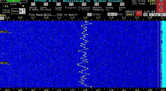
A few examples of interesting signals appear in the Figures. Figure 3 is a phenomenon previously observed on several occasions by professional SETI scientists. Project Phoenix scientist Dr. Jill Tarter had seen them from the Parkes radio observatory, dubbed them "Wigglers" [5], and concluded that they represented a form of terrestrial interference. When Project Argus participants began to observe wigglers, they performed extensive collaborative analysis, and determined that they were L-band electromagnetic emissions originating within the very computers being used for digital signal processing! The troubleshooting challenge is evident, in that shutting down the computer ends both the interference and all documentation thereof. Wigglers in Project Argus stations were finally isolated to a particular model of Adaptec SCSI card. By standardizing our stations on ISA and PCI, as opposed to SCSI, interface, the problem has been resolved.
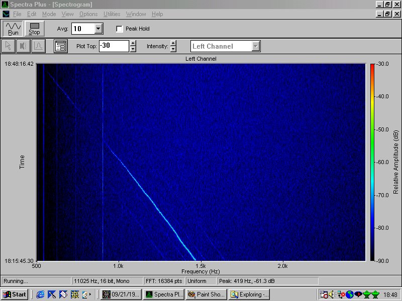
Figure 4 shows the detection by the author's personal Project Argus station of the low-power, spread-spectrum L2 signal from a Global Positioning Satellite. Conventional wisdom holds that these signals, intended for secure military use, are undetectable by any observer not possessing the encoding key. SETI critics use the existence on Earth of spread spectrum technology as "proof" that signals from other advanced civilizations will not be detectable by us. But in fact, the L2 signal is seen to be clearly discernible well above the noise level. In fact it is decoding of such encrypted signals which is beyond our capability. Figure 4 demonstrates clearly that detection, which is what SETI's quest for existence proof is all about, is trivially easy, providing signal strength is adequate.
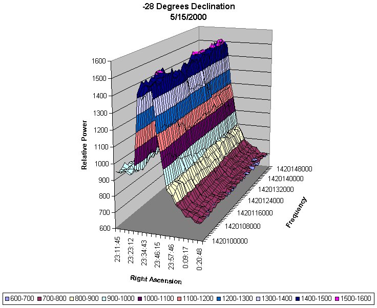
Figure 5 is an example of how equipment anomalies can masquerade as valid SETI candidates. It is a wideband artifact, tens of kHz wide, which rises out of, and falls back into the noise at a rate exactly matching the drift-scan pattern of the antenna being used in meridian transit mode. After months of repeats and analysis, the SETI League member detecting this artifact traced it to thermal instability in his receiver, which caused the noise floor to rise and fall in a deceptively periodic manner. None of the signals detected thus far is the existence proof of other intelligences, which is SETI's ultimate goal. Should a signal of probable intelligent extraterrestrial origin be detected, its existence will be confirmed by multiple observers, and it will be subject to the utmost scrutiny by amateur and professional SETI scientists alike [6] before The SETI League even considers announcing it to a waiting world.
FUTURE PLANS
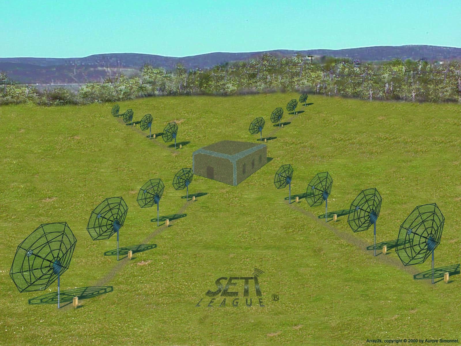
Although an abundance of small dishes can, if properly coordinated, provide unprecedented sky coverage, it is when they are working as a unified whole that they will achieve their ultimate potential. SETI League engineers are currently doing preliminary conceptual work on Array2k (see Figure 6), a phased array of sixteen standard satellite TV dishes with a total of 2000 square feet of capture area. When built, Array2k will exhibit performance on a par with a single 50 foot radio telescope. It will serve as a test-bed for new SETI League hardware, as well as the software which will ultimately allow Project Argus participants around the world to participate in our next major project, an antenna of global proportions dubbed Project ELBA (for Extremely Long Baseline Array). Array2k will also follow the example of the SETI Institute's Project Phoenix, by serving as a Follow-Up Detection Device (FUDD) for verifying the signals detected by individual Project Argus participants.
CONCLUSION
With one hundred up, and 4900 to go, Project Argus is already doing credible science. This amateur effort is also functioning as a training ground for the next generation of SETIzens, and as a test bed to develop new technologies. The SETI League is proud that our professional colleagues have followed our lead, in considering the use of inexpensive satellite TV dishes for SETI. We wish the SETI Institute and the University of California well in the development of their ambitious One Hectare Telescope, confident that it will lead to productive collaboration between SETI amateurs and professionals worldwide.
email the Webmaster | entire website copyright © The SETI League, Inc. this page last updated 22 April 2003 |
Top of Page |