 Publications Department
ABSTRACT
For the past two years, the SETI community has marveled at the development of the ambitious Paul Allen Telescope, a mini-Cyclops consisting of up to a thousand phased satellite TV-type dishes. While saluting the efforts of our California colleagues, The SETI League has been hard at work on its own phased array design, more modest in scope but quite as technologically audacious. When completed, Array2k (patent pending) will employ a unique mix of analog and digital techniques to operate in five distinct modes simultaneously. Optimized as a drift-scan sky survey instrument in the proud tradition of Ohio State's Big Ear, it will serve as its own Follow-Up Detection Device, verifying its own findings in real time.
INTRODUCTION
The SETI League, Inc. launched its Project Argus all-sky survey in April 1996, with the ambitious goal of real-time all-sky coverage (Shuch, 1997). Our experience in implementing a global network of small radio telescopes (Shuch, 2000) has underscored the importance of developing larger scale telescopes with improved sensitivity. Due to negative economies of scale, we early decided to explore the arraying of a quantity of the very type of antennas used in the current Project Argus network -- that is, extrapolating from our area of greatest expertise.
The technological breakthroughs described here may be applied generally to radio astronomy, and the microwave antenna arrays and systems utilized in such installations. More particularly, the present invention describes a multi-dish antenna array primarily adapted for astrophysical research and the Search for Extra-Terrestrial Intelligence (SETI). We have named our proposed antenna Array2k, not for the year past, or the much-feared computer crisis, but rather in recognition of its 2,000 square feet of collecting area, which can be expected to yield performance equivalent to that of a single 50-foot dish, but at perhaps a tenth the cost.
THE NEED FOR MULTIPLE MODES
It has long been recognized by those skilled in the art that multiple antennas can be combined together for increased receiver performance. The advantages are numerous and well known. Various forms of prior art technology exist for combining the antennas.
For example, in astrophysical research and the electromagnetic Search for Extra-Terrestrial Intelligence (SETI), it has been the common practice to combine multiple dish antennas into an array, optimized to produce a specific beam geometry. Beam geometries tend to be highly application-specific. For example, drift-scan SETI receiving stations are best served by an antenna pattern that is somewhat broader in the declination axis than it is in right ascension. This very type of beam pattern was implemented by the late Ohio State University "Big Ear" radio telescope, circa 1964 - 1997, which was one of the great pioneers in SETI. Total power studies of the galactic core favor an opposite antenna pattern (that is, a geometry which is broader in right ascension than it is in declination). Targeted searches of individual stars and quasi-stellar objects require a spot beam, narrow in both planes.
At this time, in order to achieve a given beam patter, distinct, application-specific arrays of antennas are used. Obviously this approach has limitations when funds are limited, and only one array is practicable. Alternatively, antennas may be physically relocated. Obviously this approach is difficult, and sometimes proves impractical. For example, the twenty-seven dish antennas at the 78 million dollar Very Large Array (VLA) in Socorro New Mexico each weigh 230 tons. To change this array between operating configurations, each of its dishes is moved along approximately thirty miles of railroad track.
It has long been accepted that diverse beam geometries tend to be mutually exclusive. An adaptive antenna array, one that can operate in multiple geometric modes simultaneously, would be highly advantageous.
REVIEW OF PRIOR ART
The advantages gained by combining multiple antennas into an array are well known, and fall into two broad categories: (a) improving sensitivity, and (b) improving resolution. The two most common ways of connecting multiple antennas into an array are (a) as a radiometer, and (b) into correlation detectors. (Burke and Graham-Smith, 1997).
In the case of the radiometer connection, a single detector is connected to all of the antennas in the array via a branched feedline, which maximizes sensitivity by producing a single beam. The best known (though never implemented) example of this configuration is Project Cyclops (Oliver et. al., 1973).
In an interferometer (Ryle, 1952) resolution is improved by combining the signals of two antennas which are separated by a specified distance (called the baseline). With dish antennas, the resulting gain is simply that which would be achieved by a single dish with a surface area equal to the sum of that of the two antennas. However, the angular resolution of such an interferometer is equivalent to that of a single dish with a diameter equal to the baseline. Thus, interferometers provide a modest improvement in sensitivity with a much greater increase in resolution.
A multiple-antenna interferometer array may be constructed using a technique known as aperture synthesis. Each possible pairing of antennas in the array is accomplished by applying the outputs of the antennas to a multitude of correlator circuits. The correlator outputs may be combined to produce multiple beams, making it possible to image distant astrophysical objects with high levels of detail.
Well-known multiple-antenna interferometers include the Very Large Array (Napier et. al., 1983) and the Giant Meter-Wave Radio Telescope (Swarup et. al., 1991). Both of these arrays arrange their antennas (27 in the case of the VLA; 30 at the GMRT) in a "Y" configuration with extremely wide baselines, and use digital correlators to combine the signals from the multiple dishes.
The Mills Cross arrangement (Mills, 1963) consists of two line-type antennas, one oriented North-South and the other East-West. The former antenna produces a beam pattern which is narrow in declination and broad in right ascension. The latter produces a beam pattern which is broad in declination and narrow in right ascension. When signals from the two antennas are combined, a beam is produced which is narrow in both axes. Bracewell and Swarup (1961) produced an array of 32 small parabolic dish antennas, oriented in a Mills Cross, to produce a pencil-beam interferometer with micro-steradian resolution.
All of the antenna arrays described above achieve stated design goals of high sensitivity or high angular resolution. In each case, one and only one of these design objectives can be achieved, and invariably at the expense of the other.
The present invention resembles the Bracewell and Swarup array in physical configuration. Unique circuitry is added to allow it to operate both as a total-power radiometer, and as a correlated interferometer, simultaneously. The multiple operating modes envisioned will allow the array to achieve both high sensitivity and high angular resolution, allowing it to fulfill a variety of research objectives.
ARRAY2K DESIGN OBJECTIVES:
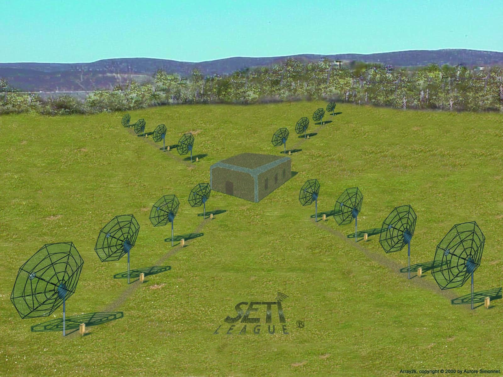
Array2k is an array of small, dish antennas all interconnected to accomplish specific beam patterning. As currently envisioned, the array comprises 16 individual parabolic dish antennas, each four meters in diameter. Four sub-arrays, each with four individual antennas, are established in a cross-like formation, with one sub-array each running north, south, west and east of the array's phase center.
We propose a means for electronically changing a complex multiple-antenna array into different configurations for producing different beam patterns. In other words, radio signals derived from the sub-arrays can be analog-processed and combined into control signals that are useful for generating steering parameters. Control signals are synthesized through a combination of analog signal quadrature techniques, combined with digital conversion and software correlation. As different individual antennas forming each sub-array monitor at least portions of overlapping sky viewed by others, quadrature processing of signals derived from each individual antennas can be processed not only to yield the composite observed target sought by the radio telescope, but can be correlated to generate the required steering parameters to observe the desired beam patterns.
The basic objectives of this design are:
The following descriptive sections show how we intend to meet the above objectives.
ARRAY2K PHYSICAL CONFIGURATION:
Figure 1 shows an artist's rendering of the preferred embodiment of the Array2k concept. The sixteen antennas depicted consist of parabolic reflectors four meters in diameter. The antennas are physically arranged in rows that emanate outwardly from a specified, central location (known as the array phase center). A laboratory building sheltering computers and other components of the array will occupy the phase center. Four sub-arrays are oriented along baselines radiating outwardly from the array center, in the directions of true North, South, East and West. Ideally each sub-array comprises four individual antennas, equally spaced at two dish diameters. These groups of four identical antennas each are known as the East, West, North and South sub-arrays.
The five planned operating modes are depicted in Figure 2. Through use of a combination of analog and digital signal combining techniques, Array2k will simultaneously produce:
FEED ASSEMBLY:
Figure 3 shows the prime-focus feed assembly mounted to each of the sixteen dishes in the array. Note that each feed assembly consists of a cylindrical waveguide feedhorn (with choke ring) operational over the array's 1.3 to 1.7 GHz intended bandwidth. The feedhorns are fitted with two orthoginally polarized monopole probes, for dual linear polarization, mounted to the center pin of type N coaxial connectors. Gain and phase matched low noise amplifiers (LNAs) are attached to the two probe connectors via identical short lengths of low-loss coaxial cable.
Again using identical low-loss cables, the outputs of each pair of preamplifiers are connected to a microstrip quadrature detector and dual in-phase power splitter assembly, to produce two RHCP signals (referred to here as Phased and Combined), and two LHCP signals, similarly labeled. The phased outputs will be used downstream for digital correlation, and the combined signals will drive analog combiner circuitry, as described in the following Sections.
It is important to note that the success of this array depends upon precise phase and gain matching of all 32 LNAs in the system, not only across the operating frequency spectrum, but also over temperature and with changes in applied operating potential. The use in all LNAs of monolithic microwave integrated circuits (MMICs) from the same production wafer, and microstrip circuit boards etched from the same physical substrate stock, is contemplated. For consistency, it is expected that any spare LNAs likely to be needed over the life of the array will have to be manufactured in the same production run as those initially placed into service.
ANALOG SIGNAL COMBINERS:
As seen in Figure 4, for each of the four sub-arrays, the RHCP an LHCP combined signal outputs from Figure 3 are combined in an x-way analog power combiner (where x equals four for the sixteen-dish array described here, but for larger n-dish arrays will be n/4). The combined signals representing each of the four sub-arrays are then split into two identical signal components, A and B in Figure 4.
The first of these components from each sub-array (A in Figure 4) is applied to the network of quadrature couplers shown at the top of Figure 5, to produce the broad-beamwidth combined response shown as Pattern A in Figure 2.
The other of the two identical power-split components from each sub-array (B in Figure 4) is then applied to the network of in-phase power combiners shown at the bottom of Figure 5, thus producing for each circularity the beam responses shown as Patterns B, C, and D in Figure 2.
Note that the above process is repeated for both orthogonal circular polarizations, producing thus far a total of eight beam responses from the array: four RHCP and four LHCP. Collectively, the circuitry described thus far supports multiple search strategies.
DIGITAL CORRELATORS:
The circuitry shown in Figures 2 through 6 utilizes analog techniques to provide four of the five operating modes proposed for Array2k. The fifth mode, a real-time fully steerable spot beam, requires that we employ digital correlation techniques. The required correlator circuitry is the least fully developed aspect of the present project. A very preliminary blueprint of the planned correlator is shown as Figure 6.
Signal samples from each antenna, and in each circular polarization, were generated as shown in Figure 3, and were previously designated "Phased Signals." Each of the 16 RCHP Phased signals and 16 LHCP Phased signals is first applied to its own individual Analog-to-Digital Converter (ADC). Each ADC digitizes the analog signals delivered thereto, and preserves amplitude and phase information, thus producing simultaneous RHCP and LHCP digital signal representations.
Each of a pair of 16-input digital signal correlators is driven by the RHCP and LHCP digital signal representations supplied by the ADCs. Each correlator is controlled by and provides its data output to a beam steering and data analysis computer, and thence a to mass data storage means, as depicted in Figure 6. The software that controls the electrical phases of all digitized signals in the entire array produces a spot beam E (Fig. 2) electrically steerable anywhere within the overall beamwidth A of the original sixteen antennas.
PROJECT STATUS:
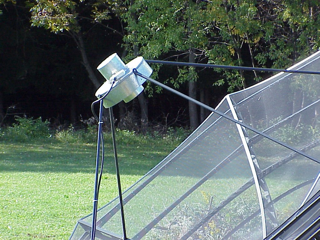
To date, Array2k is very much vaporware, as the project is yet to be funded. A single-dish prototype (see Figure 7) has been on the air for two years in North Central Pennsylvania, implementing the circuitry shown in Figure 3, and validating our hardware choices for the parabolic dish, feed assembly, mounting method, and rotors.
A suitable piece of land has been donated to the project. Located on a remote ostrich farm in northern New Jersey, the planned site represents the best in compatible land use planning, as the area is far from industry and its accompanying electromagnetic interference, and ostriches are not known to emit electromagnetic radiation of their own. In addition, the ostrich farm provides an eloquent metaphor for the mentality of those policy makers who have terminated the funding of past SETI projects.
We contemplating implementing beam patterns A through D first, and then applying the 32 "combined signal" outputs from the feed assemblies (Figure 3) to the correlator system as it evolves, to produce pattern E. We choose to tackle the analog combining modes first because the required microwave circuitry is a mature technology, whereas the digital techniques and computer power required in this last phase are still evolutionary. It is hoped that by the time Modes A through D are active some months to years downstream, more capable and affordable digital solutions will present themselves.
FINANCIAL CONSIDERATIONS:
Economic tradeoff analysis (see Figure 8) suggests that total array costs are minimized when investments in steel and silicon are roughly equal. In the case of Array2k, this sets for us the optimum size, as well of the number, of the individual antennas to achieve a given level of performance. Array2k promises a roughly one order-of-magnitude improvement in performance over existing individual Project Argus stations, at a cost increment only slightly greater that one order of magnitude. When the costs of the electronics and the mechanical systems are set roughly equal, the budget in Table 1 results. Thus, our present task is to raise the required $160,000 to turn this system into reality.
Our colleagues in other SETI organizations have wondered why after a year of prototyping and design, The SETI League, Inc. chose in early August of 2000 to apply for a patent on Array2k. We are a membership-supported nonprofit organization receiving no Government funds whatever. Though our cadre of volunteer engineers can come up with clever designs, the actual construction of Array2k is clearly beyond our means. We will certainly share our technology with like-minded researchers, just as other SETI organizations have shared generously with us. But if there are any potential commercial applications to the technology disclosed in our patent, we can hope perhaps to generate through the patent process sufficient royalty funds to finance the construction of our own array.
CONCLUSION:
It always comes down to money, doesn't it? The SETI League, Inc. stands ready to place its Array2k system on the air (at least in its first four operating modes) within a year of the project being funded. All we need now is a discretionary $160,000 -- pocket change to professional scientific endeavors, to be sure, but all the money in the world to a group of dedicated amateurs seeking to do breakthrough science with cutting-edge facilities of their own design.
Perhaps this paper will help to bring the required funding, and hence Array2k, closer to reality.
REFERENCES:
Bracewell, R. N., and G. Swarup, The Stanford microwave spectroheliograph antenna: a pencil beam interferometer, IRE Trans. Antennas and Propagation, vol. AP-9, pp. 22-30, January 1961.
Burke, B. F., and F. Graham-Smith, An introduction to radio astronomy, Cambridge University Press, 1997.
Mills, B. Y., Cross-type radio telescopes, Proc. IRE Australia, vol. 24, pp. 132-140.
Napier, P. J., A. R. Thompson and R. D. Eckers, The very large array, design and performance of a modern synthesis radio telescope, Proc. IEEE, vol. 71 no. 11 pp. 1295-1320, Nov. 1983.
Oliver, B. M., and J. Billingham, eds., Project Cyclops, a design study of a system for detecting extraterrestrial intelligent life, NASA CR 114445, 1973.
Ryle, M., A new radio interferometer and its application to the observation of weak radio stars. Proc. Royal Soc. London Ser. A, vol. 211, pp. 351-375, 1952.
Shuch, H. P., Project Argus and the challenge of real-time all-sky SETI, in Astronomical and biochemical origins and the search for life in the universe, IAA Colloquium 161, 693 - 700, 1997.
Shuch, H. P., Project Argus: one hundred up, 4900 to go! IAA-00-IAA.9.1.04, Oct. 2000.
Swarup, G., S. Ananthakrishnan, V. K. Kapahi, A. P. Rao, C. R. Subrahmanya, and V. K. Kulkarni, The giant metre-wave radio telescope, Current Science, vol. 60 no. 2 pp. 95-105, 25 January 1991.
|
Figure 1
Array2k Artist's Rendering
Figure 2
Beam Pattern, plotted in Elevation vs. Azimuth,
of the Adaptive Microwave Array it its five operating modes.
Figure 3
Array2k Feed Assembly (one used on each of the sixteen dishes)
Figure 4
In-Phase Analog Power Combiner Assembly (LHCP East sub-array combiner is shown).
Similar assemblies will be used for both orthogonal circular polarizations on all four sub-arrays.
Figure 5
Sub-Array Combiners
(RHCP shown. A similar assembly is used on each of the LHCP sub-array outputs.)
Figure 6
Digital Correlator Assembly for Aperture Synthesis
Figure 7
Single-dish prototype for the Array2k antennas, mounts, rotors, and feed assembly
Figure 8
Economic tradeoff analysis for an N-dish array
email the Webmaster | entire website copyright © The SETI League, Inc. this page last updated 28 December 2002 |
Top of Page |